|
LCD meter, using a single PIC.
![]() I've
had a lot of feedback about my original LCD meter project, and I've emailed
the original software to a number of people who asked for it. However, the
project never got completed - basically because MicroChip brought out new
PIC's which rendered the original project obsolete. Whereas the original
project used a 16F84 and a 12C672, the more modern 16F818/9 provides 10 bit
A2D in the same 18 bit package as the 16F84 uses, and also has an internal
oscillator - removing the need for a crystal and associated capacitors.
I've
had a lot of feedback about my original LCD meter project, and I've emailed
the original software to a number of people who asked for it. However, the
project never got completed - basically because MicroChip brought out new
PIC's which rendered the original project obsolete. Whereas the original
project used a 16F84 and a 12C672, the more modern 16F818/9 provides 10 bit
A2D in the same 18 bit package as the 16F84 uses, and also has an internal
oscillator - removing the need for a crystal and associated capacitors.
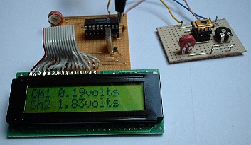
![]() This
makes the entire project even simpler, reducing it to the LCD display, one
16F818/9, one potentiometer, one decoupling capacitor, and (optionally) a
TL341 voltage reference and feed resistor. It also makes the software
simpler, as we don't need to communicate between the two IC's. My newer LCD
routines are much improved, working in 4 bit mode and using hardware timing,
rather than simple delay timing - this ensures the LCD routines are as fast
as possible. The routines are actually those I developed for my PIC
Tutorials at
http://www.winpicprog.co.uk, and the entire meter software is based on
the analogue to digital converter tutorial on those pages.
This
makes the entire project even simpler, reducing it to the LCD display, one
16F818/9, one potentiometer, one decoupling capacitor, and (optionally) a
TL341 voltage reference and feed resistor. It also makes the software
simpler, as we don't need to communicate between the two IC's. My newer LCD
routines are much improved, working in 4 bit mode and using hardware timing,
rather than simple delay timing - this ensures the LCD routines are as fast
as possible. The routines are actually those I developed for my PIC
Tutorials at
http://www.winpicprog.co.uk, and the entire meter software is based on
the analogue to digital converter tutorial on those pages.
 |
|
|
|
 |
 |
|
 |
|
![]() The
software in the 12C672 reads the first input (AD0) and then multiples the
result by 195 to scale the 0-255 result to 0-50000, the resulting
value is then converted into a decimal string, with the lowest two digits
discarded. The decimal numbers are next converted to their ASCII codes, a
decimal point added, and the data sent out as standard 9600baud serial data,
cursor positioning commands are also added to the data stream, and the
various text additions as seen in the pictures. Once AD0 has finished, the
same is done for AD2, and the program then loops back to the start to give
continuous updates.
The
software in the 12C672 reads the first input (AD0) and then multiples the
result by 195 to scale the 0-255 result to 0-50000, the resulting
value is then converted into a decimal string, with the lowest two digits
discarded. The decimal numbers are next converted to their ASCII codes, a
decimal point added, and the data sent out as standard 9600baud serial data,
cursor positioning commands are also added to the data stream, and the
various text additions as seen in the pictures. Once AD0 has finished, the
same is done for AD2, and the program then loops back to the start to give
continuous updates.
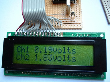
![]() The
16C84 reads the data stream, and displays the incoming data, the cursor
positioning commands are striped out and processed separately - command and
display functions are driven separately on these LCD modules. In order to
detect command data, I first send a non-printing character (in this case
0x80) followed by the required data byte - the 16C84 detects the 0x80 and
jumps to a command routine which send the following byte to the display as a
command.
The
16C84 reads the data stream, and displays the incoming data, the cursor
positioning commands are striped out and processed separately - command and
display functions are driven separately on these LCD modules. In order to
detect command data, I first send a non-printing character (in this case
0x80) followed by the required data byte - the 16C84 detects the 0x80 and
jumps to a command routine which send the following byte to the display as a
command.
![]() I'll
be adding the software listings once I've decided exactly what I want to do,
I'm open to any suggestions?.
I'll
be adding the software listings once I've decided exactly what I want to do,
I'm open to any suggestions?.