A Cybot IR Obstacle Detector
Board
 This
latest board adds obstacle avoidance to Cybot, in a similar way to the
ultrasonic system Cybot will use in later issues, but this uses Infra Red
object detection instead. It's a fairly standard technique, most modern
small robots use it (Ultrasonic is rather old, and expensive!, but has the
advantage that you can actually measure distance - light is too fast!). Basically
you have two IR emitters, and one IR receiver in between them, you
transmit a signal from one, and check for a reflected signal coming back,
you then transmit on the other emitter, and check again - in this way you
can detect objects to the left, right, or in front (both sides). This
latest board adds obstacle avoidance to Cybot, in a similar way to the
ultrasonic system Cybot will use in later issues, but this uses Infra Red
object detection instead. It's a fairly standard technique, most modern
small robots use it (Ultrasonic is rather old, and expensive!, but has the
advantage that you can actually measure distance - light is too fast!). Basically
you have two IR emitters, and one IR receiver in between them, you
transmit a signal from one, and check for a reflected signal coming back,
you then transmit on the other emitter, and check again - in this way you
can detect objects to the left, right, or in front (both sides).
 |
 |
Parts List
| IC1 |
PIC12C508 |
| IC2 |
TFMS5360 |
| IRL, IRR |
RS 195-669 |
| LL, LR |
Red LED's |
R1, R2,
R3, R4 |
1KOhm |
| R5 |
10KOhm |
| R6 |
47Ohm |
| C1 |
47uF 16V |
| C2 |
10uF 25V |
| Veroboard |
14 x 17 |
|
 I
had planned to design my own detector system, using a 16C(F)84, but I
happened to find an excellent design on the web at http://www.verinet.com/~dlc/
- and this is far better than I was planning, it uses a fairly complex
'voting' system to help get reliable detection, and works extremely well.
It uses a PIC12C508, which is an 8 pin OTP PIC, fortunately I have the
capability of programming this chip, so I was able to blow my own chip.
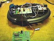
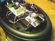
The author sells PCB's and programmed chips, but I built it on veroboard. The pictures above give you
some idea of how it looks, the detector board at the front is presently
only held in position by the wires, I'm considering using a lump of
Blutack to hold it in place I
had planned to design my own detector system, using a 16C(F)84, but I
happened to find an excellent design on the web at http://www.verinet.com/~dlc/
- and this is far better than I was planning, it uses a fairly complex
'voting' system to help get reliable detection, and works extremely well.
It uses a PIC12C508, which is an 8 pin OTP PIC, fortunately I have the
capability of programming this chip, so I was able to blow my own chip.
The author sells PCB's and programmed chips, but I built it on veroboard. The pictures above give you
some idea of how it looks, the detector board at the front is presently
only held in position by the wires, I'm considering using a lump of
Blutack to hold it in place  . The shield over the sensor is just a
piece of black card, held in place by a couple of blobs of hotmelt glue.
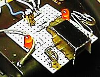
The IR LED's are mounted with the leads full length, so you can
aim them to get the detection pattern as you want it, you could
also add short lengths of black tubing over the LED's to reduce
the beam width if required. You can download the software from DLC IR proximity detector. . The shield over the sensor is just a
piece of black card, held in place by a couple of blobs of hotmelt glue.
The IR LED's are mounted with the leads full length, so you can
aim them to get the detection pattern as you want it, you could
also add short lengths of black tubing over the LED's to reduce
the beam width if required. You can download the software from DLC IR proximity detector.Unfortunately
the original site has disappeared now, so here's a local link to the
assembler code for the 12C508 - download nirprox.asm |
 This
is my redrawn version of the circuit diagram, I used a TFMS5360 IR
detector IC, it's commonly used in the UK in many TV's, including
Tatung and Grundig. You can use pretty well any IR detector IC,
just be aware that they don't all use the same connections. R1 and
R2 set the current through the IR LED's, you can alter the
detection range by changing the values of these - make them larger
to reduce the range. The IR LED's are the type used in TV
handsets, I got them from RS Components, type LD274, part number
195-669. The two other LED's are
normal visible ones, and they serve simply to give a visible
indication of how the detector is working, and can be left out
(along with R3 & R4) if not required. Personally I find them
extremely useful, and they allow you to test the detector without
having it connected to anything else - it's also interesting to
watch them go on and off as Cybot moves around!. The Enable pin
isn't used, it simply turns off the detector when taken low, and
if left unconnected is pulled high by R5 - but I find it useful to
have the LED indication working even when not in use!. This
is my redrawn version of the circuit diagram, I used a TFMS5360 IR
detector IC, it's commonly used in the UK in many TV's, including
Tatung and Grundig. You can use pretty well any IR detector IC,
just be aware that they don't all use the same connections. R1 and
R2 set the current through the IR LED's, you can alter the
detection range by changing the values of these - make them larger
to reduce the range. The IR LED's are the type used in TV
handsets, I got them from RS Components, type LD274, part number
195-669. The two other LED's are
normal visible ones, and they serve simply to give a visible
indication of how the detector is working, and can be left out
(along with R3 & R4) if not required. Personally I find them
extremely useful, and they allow you to test the detector without
having it connected to anything else - it's also interesting to
watch them go on and off as Cybot moves around!. The Enable pin
isn't used, it simply turns off the detector when taken low, and
if left unconnected is pulled high by R5 - but I find it useful to
have the LED indication working even when not in use!. |
 This
is the veroboard layout, as drawn by Stripboard Magic, with the
circuit above it should be easy to workout what goes
where. The two red dots are track breaks, there are also four more
under the IC, between the pins. The gray dots at the left are the
connections to the receiver board, from top to bottom they are 5V,
left detect, right detect, enable (not currently used), and
ground. The middle three at the right are where the IR detector
goes, I used a
TFMS5360, the top and bottom pairs of dots are for the IR emitters.
I connected to the receiver board by adding four veropins, on 5V,
Gnd, and pins 12 and 13 of the PIC.
This
is the veroboard layout, as drawn by Stripboard Magic, with the
circuit above it should be easy to workout what goes
where. The two red dots are track breaks, there are also four more
under the IC, between the pins. The gray dots at the left are the
connections to the receiver board, from top to bottom they are 5V,
left detect, right detect, enable (not currently used), and
ground. The middle three at the right are where the IR detector
goes, I used a
TFMS5360, the top and bottom pairs of dots are for the IR emitters.
I connected to the receiver board by adding four veropins, on 5V,
Gnd, and pins 12 and 13 of the PIC. |
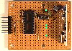 To connect the receiver board to the sensor board, I fitted four
veropins to the existing receiver board, they are marked as green
circles in this picture. The top green circle is ground, then left
detect, right detect, with 5V at the bottom. To connect the receiver board to the sensor board, I fitted four
veropins to the existing receiver board, they are marked as green
circles in this picture. The top green circle is ground, then left
detect, right detect, with 5V at the bottom.
In
use it's combined with my remote control system, this works the same as
before, but one of the buttons now activates the obstacle avoidance
function. If it gets stuck, you can just press the remote buttons and
extricate it manually, then switch back to obstacle avoidance mode
afterwards.
I'll
be adding example software here as well, presently it's fairly crude -
but it uses only a few lines added to the original RX code. Basically it
checks for the left detector being triggered, if so it turns right, if not
it checks the right detector, and if triggered turns left - if neither is
triggered it goes forward. If both are triggered it goes left, as it
checks that detector first - I'm still thinking what to do if both sensors
are triggered, perhaps spin it rather than just turning? - I'm open to
suggestions!. Following on from that, and after a suggestion from someone,
I've altered the software so it spins when both detectors are triggered,
it does this in either direction, chosen at random - once it starts
spinning, it will continue to do so, until the sensor furthest from the
spin is cleared - be aware - while it's doing this it's sat in a loop, so
it doesn't check the R/C signal, and you can't abort it until it exits the
loop!.
|
|

