  Cybot's
'Line Follower' mode uses a pair of IR sensors aimed downwards close to
the floor, these feed to the two inputs of an LM311 comparator, the output
of which feeds to the Processor 1 board, using pin 11 of the chip for the
actual input. The sensors themselves consist of an IR LED and an adjacent
photodiode (built as a single unit), so the light Cybot's
'Line Follower' mode uses a pair of IR sensors aimed downwards close to
the floor, these feed to the two inputs of an LM311 comparator, the output
of which feeds to the Processor 1 board, using pin 11 of the chip for the
actual input. The sensors themselves consist of an IR LED and an adjacent
photodiode (built as a single unit), so the light 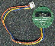 from the IR LED is
reflected back by a light coloured surface, and absorbed by a dark
coloured surface - the photodiode responding to the amount of light reflected
back. On Cybot this is done fairly crudely, for good performance more
sensors are needed, as it stands with only the two sensors Cybot can only
follow a black/white transition, so it actually follows the edge of the
line (one sensor on black, one sensor on white) - this gives it the slow jerky response seen in the video supplied in
one of the early issues. A better way to do it, though more expensive, is
to use a minimum of three sensors, with the outer two spaced according to
the width of the line, and the third in the middle - in this way you can
follow the centre of the line, in a much smoother fashion, the middle
sensor detects the line, and the outer two detect the background - even
more sensors can be used to further improve the performance. As well as
the sensors there are three surface mount resistors on the board, R1 is
270ohm, and limits the current to the LED's - giving about 10mA of drive.
The other two, R2 and R3, are both 8.2Kohm, and provide a bias voltage for
the photo diodes - the more reflected IR light the photodiodes receive,
the more current they draw, and the lower the voltages at the bottom ends
of R2 and R3. from the IR LED is
reflected back by a light coloured surface, and absorbed by a dark
coloured surface - the photodiode responding to the amount of light reflected
back. On Cybot this is done fairly crudely, for good performance more
sensors are needed, as it stands with only the two sensors Cybot can only
follow a black/white transition, so it actually follows the edge of the
line (one sensor on black, one sensor on white) - this gives it the slow jerky response seen in the video supplied in
one of the early issues. A better way to do it, though more expensive, is
to use a minimum of three sensors, with the outer two spaced according to
the width of the line, and the third in the middle - in this way you can
follow the centre of the line, in a much smoother fashion, the middle
sensor detects the line, and the outer two detect the background - even
more sensors can be used to further improve the performance. As well as
the sensors there are three surface mount resistors on the board, R1 is
270ohm, and limits the current to the LED's - giving about 10mA of drive.
The other two, R2 and R3, are both 8.2Kohm, and provide a bias voltage for
the photo diodes - the more reflected IR light the photodiodes receive,
the more current they draw, and the lower the voltages at the bottom ends
of R2 and R3.
|

