A Cybot Radio Control PIC TX Board
 Following
on from my original PIC board, I've now started to develop a UHF radio
control link, to provide Cybot with a versatile remote control system.
This page describes the on-going development of the PIC transmitter board
on a PIC prototype board, the hardware is now fully functional, the
software is still under development, but works fairly well. Following
on from my original PIC board, I've now started to develop a UHF radio
control link, to provide Cybot with a versatile remote control system.
This page describes the on-going development of the PIC transmitter board
on a PIC prototype board, the hardware is now fully functional, the
software is still under development, but works fairly well.
For
a change, I've used a ceramic resonator on this prototype board (but
I specify a crystal in the parts list and circuit), I must have had
one to hand when I assembled it. The radio module can be ordered from RS
Components at http://rswww.com - the
matching transmitter is part number 376-6539. They cost just over
£20+vat, and work at 433MHz FM, give up to 250 meters range, and
provide up to 9600 baud data rate.
 |
Parts List
| UHF Transmitter |
RS 376-6539 |
| Processor |
PIC16F84 |
| Crystal |
4MHz |
| C1, C2 |
10pF |
| C3, C4, C5 |
10uF |
| REG1 |
78L05 |
| R1 (as required) |
22K |
| SW1 (as required) |
PB switch |
|
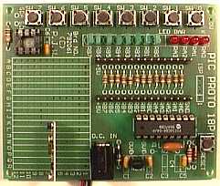 |
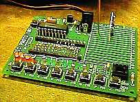
This is a picture of the
prototype board I'm using for developing the software, the
transmitter is at the lower left. I got it at Elvaston Castle Radio Rally a
number of years ago, it's from PJW
Design. At the time of this picture the switches aren't wired, I'm
simply transmitting test data bytes. |
|
Now
I'm down to writing the software, I've never played with these data
modules before, but I'm aware that there are a number of problems not
found when doing a serial link down a piece of wire!.
Firstly you can't send a continuous high level, after a certain time the
output of the receiver switches randomly between high and low, and then
settles in the low position, so my initial change is to invert the data
from the PIC, so it stays low normally (the opposite was true in my
original RS232 routines). Having done this, I've been doing simple tests
sending two bytes of data (actually 0xAA and 0xFF), separated by a low
level for 20 bit-times. I monitored both the input to the transmitter, and
the output from the receiver, using a 20MHz double beam oscilloscope, this
showed that the receiver was outputting an accurate replica of the
transmitted signal. I tried the scope with the data the other way, with a
high between the data bytes, and about half way between the bytes the
signal corrupted and fell to a low level.
|
|
 Secondly
you can't rely on 100% reliability, any interference, or obstruction
between TX and RX could give data loss, either one bit or more, so it
becomes difficult to be sure you are starting reading at the beginning of
the data byte. I'm currently considering how I might best overcome this
problem, searching the net I've found some interesting schemes for this,
but I've not yet decided how I'm going to do it. I'm open to
suggestions if anyone has any simple workable schemes?. At the moment
I'm considering simply maintaining a long gap between data bytes, I could
then wait for a low period of this length before looking for a start bit,
as I'm not looking for terribly high data transfer rates this scheme would
help to ensure correctly locating the start of the data. Secondly
you can't rely on 100% reliability, any interference, or obstruction
between TX and RX could give data loss, either one bit or more, so it
becomes difficult to be sure you are starting reading at the beginning of
the data byte. I'm currently considering how I might best overcome this
problem, searching the net I've found some interesting schemes for this,
but I've not yet decided how I'm going to do it. I'm open to
suggestions if anyone has any simple workable schemes?. At the moment
I'm considering simply maintaining a long gap between data bytes, I could
then wait for a low period of this length before looking for a start bit,
as I'm not looking for terribly high data transfer rates this scheme would
help to ensure correctly locating the start of the data.
|
Update - 29 November 2001.
 OK,
I've now played a while longer, and I've got simple working routines, I'm
not doing any error checking yet (apart from checking the stop bit is
correct), but it seems to work pretty well!. I'll try implementing the
scheme I mentioned above (waiting for a long low between reads, my
transmit routines already insert a suitably long low signal). But if you
want to try it now, the routines are here - please note these are actually
written using a couple of 16C84's (I have a number of them lying about!),
to use a 16F84 simply make the following changes at the start of the
files. OK,
I've now played a while longer, and I've got simple working routines, I'm
not doing any error checking yet (apart from checking the stop bit is
correct), but it seems to work pretty well!. I'll try implementing the
scheme I mentioned above (waiting for a long low between reads, my
transmit routines already insert a suitably long low signal). But if you
want to try it now, the routines are here - please note these are actually
written using a couple of 16C84's (I have a number of them lying about!),
to use a 16F84 simply make the following changes at the start of the
files.
Changes for C or F processor
| PIC16C84 |
PIC16F84 |
list p=16C84 , r=dec
include "P16C84.inc"
__config H'3FF9' |
list p=PIC16F84, r=dec
include "P16F84.inc"
__config H'3FF1' |
|
 The
transmit routine simply checks the condition of the 6 switches on the
transmitter, connected to PortB pins 6 to 1, and transmits a code
corresponding to which key is pressed. The receiver routine reads the
incoming code, and sets Cybot accordingly. In this test routine I have
buttons for Forward, Backward, Left, Right, and two buttons for Stop, you
can easily alter them as you wish. Once a key has been pressed, the
transmitter continually outputs that code, until you press a different
key. The
transmit routine simply checks the condition of the 6 switches on the
transmitter, connected to PortB pins 6 to 1, and transmits a code
corresponding to which key is pressed. The receiver routine reads the
incoming code, and sets Cybot accordingly. In this test routine I have
buttons for Forward, Backward, Left, Right, and two buttons for Stop, you
can easily alter them as you wish. Once a key has been pressed, the
transmitter continually outputs that code, until you press a different
key.
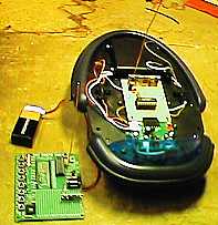
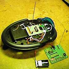
For
aerials, I'm simply using two pieces of stiff wire, about 15cm long, I
actually used the live and neutral conductors from 1.5mm twin and earth
mains cable. To use the system, turn the transmitter on first, otherwise
the random noise from the FM receiver makes Cybot do random movements.
I've
now updated the receiver software to wait for a long low level, this seems
to cure any problems, and it now doesn't matter which you turn on first.
The original routine is still there to download, and the new 'MK 2'
version is there as well. Following on from this, the latest version now
includes the PWM speed control routines, I've set the turning speed to
slow, this makes it much easier to try and point Cybot where you want to
it go.
|
|