Cybot Motor Driver Board
A description by Nigel Goodwin.
| Q3 - S8050 |
Q7 - 2SC3279 |
Q11 - 2SA1300 |
Q15 - NPN SMT |
| Q4 - S8050 |
Q8 - 2SC3279 |
Q12 - 2SA1300 |
RLED - Red LED |
| Q5 - S8050 |
Q9 - 2SC3279 |
Q13 - 2SA1300 |
GLED - Green LED |
| Q6 - S8050 |
Q10 - 2SC3279 |
Q14 - 2SA1300 |
|
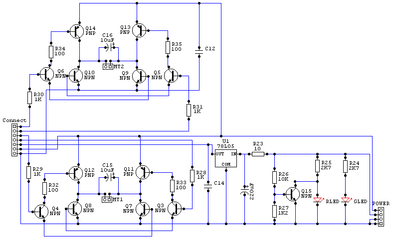
 This is the complete circuit for the Cybot driver PCB, it
consists of two simple H-Bridge drivers, one for each motor, plus a 5 volt
regulator for feeding power from the 9 volt battery to the control circuitry,
and finally two LED's - the green one shows power is turned on (from the 9 volt
battery), and the red one lights when the 9 volt battery is getting low. This is the complete circuit for the Cybot driver PCB, it
consists of two simple H-Bridge drivers, one for each motor, plus a 5 volt
regulator for feeding power from the 9 volt battery to the control circuitry,
and finally two LED's - the green one shows power is turned on (from the 9 volt
battery), and the red one lights when the 9 volt battery is getting low.
Connector details
| 7 Pin Socket |
4 Pin Socket |
MT1 |
MT2 |
1 - RH motor forwards.
2 - RH motor backwards.
3 - LH motor forwards.
4 - LH motor backwards.
5 - 5 volts to uP
6 - 6 volts
7 - ground. |
1 - ground.
2 - ground.
3 - 9 volts in.
4 - 6 volts in. |
LH Motor |
RH Motor |
 To move Cybot forwards, simply take pins 1 and 3 high (which is what the
motor test PCB does), to move backwards take pins 2 and 4 high, UNDER NO
CIRCUMSTANCES must you take pins (1 and 2) or (3 and 4) high at the same
time, this WILL destroy the output transistors!!!. To turn Cybot you have
various options, to turn left you can either take pin 1 high, or take pin 4
high, or do both - doing both will allow Cybot to spin around about it's axis - a
point midway between the rear wheels. To turn right you do the same, but use
pins 3 and 2. To move Cybot forwards, simply take pins 1 and 3 high (which is what the
motor test PCB does), to move backwards take pins 2 and 4 high, UNDER NO
CIRCUMSTANCES must you take pins (1 and 2) or (3 and 4) high at the same
time, this WILL destroy the output transistors!!!. To turn Cybot you have
various options, to turn left you can either take pin 1 high, or take pin 4
high, or do both - doing both will allow Cybot to spin around about it's axis - a
point midway between the rear wheels. To turn right you do the same, but use
pins 3 and 2.
How it works?.
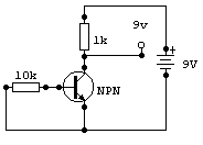
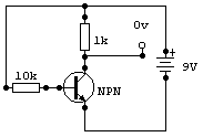
 It's a fairly straightforward circuit, the transistors are all used as simple
switches. With an NPN transistor, taking the base 'positive' of the emitter will
cause the transistor to switch on (diagram 2), taking the base to the same
potential as (or slightly below) the emitter will cause the transistor to switch
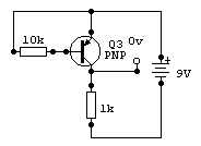
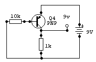
off (diagram 1) - a PNP transistor is an 'opposite' version, taking the base
'negative' of the emitter will cause the transistor to switch on. In practice a
silicon transistor requires around 0.7 volts to switch on, the low battery
circuit makes use of this in order to turn the transistor off when the battery
is running low, but the rest of the transistors are driven 'hard on' in order to
ensure they switch positively. It's a fairly straightforward circuit, the transistors are all used as simple
switches. With an NPN transistor, taking the base 'positive' of the emitter will
cause the transistor to switch on (diagram 2), taking the base to the same
potential as (or slightly below) the emitter will cause the transistor to switch
off (diagram 1) - a PNP transistor is an 'opposite' version, taking the base
'negative' of the emitter will cause the transistor to switch on. In practice a
silicon transistor requires around 0.7 volts to switch on, the low battery
circuit makes use of this in order to turn the transistor off when the battery
is running low, but the rest of the transistors are driven 'hard on' in order to
ensure they switch positively.
| Diagram 1 - NPN Off |
Diagram 2 - NPN On |
Diagram 3 - PNP Off |
Diagram 4 - PNP On |
 |
 |
 |
 |
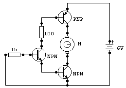
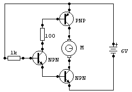
 So, looking at one section of the full driver circuit, Q4 and Q8 are NPN
(like diagram 1 & 2), and Q12 is PNP (like diagram 3 & 4). I've redrawn
this part of the circuit to make it more clear, in diagram 5 the motor is turned
off, and in diagram 6 the motor is turned on. Diagram 7 shows the effect Q4 has
when it's turned on, effectively connecting the 100 ohm resistor directly
between the base of the two transistors. So, looking at one section of the full driver circuit, Q4 and Q8 are NPN
(like diagram 1 & 2), and Q12 is PNP (like diagram 3 & 4). I've redrawn
this part of the circuit to make it more clear, in diagram 5 the motor is turned
off, and in diagram 6 the motor is turned on. Diagram 7 shows the effect Q4 has
when it's turned on, effectively connecting the 100 ohm resistor directly
between the base of the two transistors.
| Diagram 5 - motor off. |
Diagram 6 - motor on. |
Diagram 7 - simplified motor on. |
 |
 |
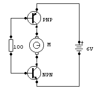 |
 Examining diagram 7 in more detail, the 100 ohm resistor connects the base of
the bottom (NPN) transistor towards the positive rail, thus turning it on, at
the same time it connects the base of the upper (PNP) transistor towards the
negative rail, thus turning that one on as well. In this way both transistors
are turned hard on, and the motor has power and rotates. With Q4 turned off, the
100 ohm in diagram 7 effectively disappears, so neither transistor is turned on,
and the motor doesn't rotate. Each motor requires two sets of this circuit, one
to rotate clockwise, and the other to rotate anti-clockwise, by selecting one or
other of the two inputs the motor is connected either way around. Examining diagram 7 in more detail, the 100 ohm resistor connects the base of
the bottom (NPN) transistor towards the positive rail, thus turning it on, at
the same time it connects the base of the upper (PNP) transistor towards the
negative rail, thus turning that one on as well. In this way both transistors
are turned hard on, and the motor has power and rotates. With Q4 turned off, the
100 ohm in diagram 7 effectively disappears, so neither transistor is turned on,
and the motor doesn't rotate. Each motor requires two sets of this circuit, one
to rotate clockwise, and the other to rotate anti-clockwise, by selecting one or
other of the two inputs the motor is connected either way around.
Lets go a little deeper!.
 I mentioned at the beginning of this article that the transistors are all
turned 'hard on', this is important as it keeps the heat generated in the
transistors to a low value, which makes it more efficient - and allows you to
use smaller, cheaper transistors. I'll demonstrate how this works with a little
bit of simple mathematics - the most important formula in Electronics is Ohms
Law, which states that Voltage equals Current multiplied by Resistance - usually
written V = I x R. I mentioned at the beginning of this article that the transistors are all
turned 'hard on', this is important as it keeps the heat generated in the
transistors to a low value, which makes it more efficient - and allows you to
use smaller, cheaper transistors. I'll demonstrate how this works with a little
bit of simple mathematics - the most important formula in Electronics is Ohms
Law, which states that Voltage equals Current multiplied by Resistance - usually
written V = I x R.
 We'll apply this formula to diagram 7, with the 100 ohm resistor - so we
already know the value of 'R' = 100 ohms. So now we need to find one of the
other two values - the only one we can do this with is Voltage, once we have
these two we can calculate the Current using Ohms Law. Now we know the battery
voltage is 6 volts, but the 100 ohm doesn't connect to the battery - BUT! it
does connect to the bases of the two transistors, whose emitters do
connect to the supply rails. Now a silicon transistor drops 0.7 volts across
it's Base Emitter junction, there's one at the top, and one at the bottom, both
dropping 0.7 volts making a total of 1.4 volts dropped. Subtract this from the 6
volt supply and we have a total of 4.6 volts across the resistor. We'll apply this formula to diagram 7, with the 100 ohm resistor - so we
already know the value of 'R' = 100 ohms. So now we need to find one of the
other two values - the only one we can do this with is Voltage, once we have
these two we can calculate the Current using Ohms Law. Now we know the battery
voltage is 6 volts, but the 100 ohm doesn't connect to the battery - BUT! it
does connect to the bases of the two transistors, whose emitters do
connect to the supply rails. Now a silicon transistor drops 0.7 volts across
it's Base Emitter junction, there's one at the top, and one at the bottom, both
dropping 0.7 volts making a total of 1.4 volts dropped. Subtract this from the 6
volt supply and we have a total of 4.6 volts across the resistor.
 So now we have two parts of the formula, and we can transpose the formula to
give I = V / R in order to find the current, so the current equals 4.6v divided
by 100 ohms which gives a current of 0.046 amps (or 46mA). This current
flows through the bases of both transistors - and a transistor works by current
gain, which means the current passing through the collector is equal to the base
current multiplied by the current gain of the transistor. So if we assume a
current gain for the transistors as low as 100 times (it's actually considerably
more than this!) we get 100 x 0.046A = 4.6A. This is more than twice the
permitted current for the devices, but will be limited by the current the motor
actually consumes, so the transistors are turned 'hard on' as required, for best
efficiency. So now we have two parts of the formula, and we can transpose the formula to
give I = V / R in order to find the current, so the current equals 4.6v divided
by 100 ohms which gives a current of 0.046 amps (or 46mA). This current
flows through the bases of both transistors - and a transistor works by current
gain, which means the current passing through the collector is equal to the base
current multiplied by the current gain of the transistor. So if we assume a
current gain for the transistors as low as 100 times (it's actually considerably
more than this!) we get 100 x 0.046A = 4.6A. This is more than twice the
permitted current for the devices, but will be limited by the current the motor
actually consumes, so the transistors are turned 'hard on' as required, for best
efficiency.
The LED's.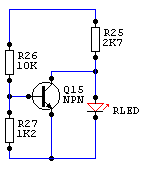
 Now
I'll explain the LED's, as you can see from the circuit above, they are wired
identically across the 9v supply, via 2.7K feed resistors. The difference is
that the red LED has an NPN transistor (Q15) connected across it, this
transistor is normally turned on, bypassing the current that would light the
LED, thus extinguishing it. The two resistors feeding the base of Q15 (R26-10K
and R27-1.2K) form a potential divider across the 9v supply so the voltage at
their junction will vary with the supply voltage (or would, if the transistor
wasn't there!). To work out the voltage at the junction, the formula is V = R27
x Battery/(R26+R27), which gives about 0.96v with a 9v supply. This circuit
works by using the turn on voltage of a silicon transistor, which is about 0.7v,
so if the base is over 0.7 volts the transistor will be on, if it's under 0.7v
it will be off. To calculate this point you can transpose the formula, to give
Battery = 0.7/R27 x (R26+R27) which works out at about 6.5v, so around 6.5v the
low battery light will start to come on, it won't be an instant transition, but
will slowly get brighter as the transistor reaches the unlinear part of it's
characteristics. Now
I'll explain the LED's, as you can see from the circuit above, they are wired
identically across the 9v supply, via 2.7K feed resistors. The difference is
that the red LED has an NPN transistor (Q15) connected across it, this
transistor is normally turned on, bypassing the current that would light the
LED, thus extinguishing it. The two resistors feeding the base of Q15 (R26-10K
and R27-1.2K) form a potential divider across the 9v supply so the voltage at
their junction will vary with the supply voltage (or would, if the transistor
wasn't there!). To work out the voltage at the junction, the formula is V = R27
x Battery/(R26+R27), which gives about 0.96v with a 9v supply. This circuit
works by using the turn on voltage of a silicon transistor, which is about 0.7v,
so if the base is over 0.7 volts the transistor will be on, if it's under 0.7v
it will be off. To calculate this point you can transpose the formula, to give
Battery = 0.7/R27 x (R26+R27) which works out at about 6.5v, so around 6.5v the
low battery light will start to come on, it won't be an instant transition, but
will slowly get brighter as the transistor reaches the unlinear part of it's
characteristics.
 I hope you find this explanation helpful, if you have any queries feel free
to contact me at nigelg@lpilsley.co.uk
or post a question on the CybotBuilder
BBS. I hope you find this explanation helpful, if you have any queries feel free
to contact me at nigelg@lpilsley.co.uk
or post a question on the CybotBuilder
BBS.
|

