Cybot Processor 2 Board
 As I
surmised back on the Processor 1 board, this board includes a 'brown out'
circuit, which cures the missing reset resistor problem on the Processor 1
board. It's a standard 'brown out' circuit, using a PNP transistor and
three resistors, the reason for using one is to help prevent problems due
to supply fluctuations, if the supply drops momentarily it could confuse
the processor, yet not drop low enough for it to generate a reset. The
'brown out' circuit overcomes this, causing a reset pulse to be generated
if the supply fluctuates enough to upset the processor. The rest of the
circuit is also standard, it uses a 4MHz ceramic resonator for the As I
surmised back on the Processor 1 board, this board includes a 'brown out'
circuit, which cures the missing reset resistor problem on the Processor 1
board. It's a standard 'brown out' circuit, using a PNP transistor and
three resistors, the reason for using one is to help prevent problems due
to supply fluctuations, if the supply drops momentarily it could confuse
the processor, yet not drop low enough for it to generate a reset. The
'brown out' circuit overcomes this, causing a reset pulse to be generated
if the supply fluctuates enough to upset the processor. The rest of the
circuit is also standard, it uses a 4MHz ceramic resonator for the 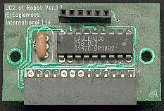 oscillator, and a total of six pull-up resistors, two of which are on the
two wire bus between the processors, and are in parallel with the similar
resistors on the Processor 1 board. The other four are on pins that connect
to the expansion connector for the next board (Sonar I/O), presumably to hold inputs
high which will be pulled low by some signals from that board - the Sonar
I/O board includes the mode switch, which is four way, so it looks like it
will feed to these pins. This gives a possible 16 values from the
switches, from '0000' to '1111' binary (0 to 15 decimal) - as Cybot still
works in 'light follow' mode, it appears that '1111' (decimal 15) is the
setting for this mode. The other
connections to the sonar I/O are via pins 2 - 6, all of which connect to
Port P6 of the processor, and the power and ground rails on pins 11 - 13. The six pin connector from the Processor 1 board
also carries a socket on top, this allows further boards to plug into it,
and connect to all the required rails.
oscillator, and a total of six pull-up resistors, two of which are on the
two wire bus between the processors, and are in parallel with the similar
resistors on the Processor 1 board. The other four are on pins that connect
to the expansion connector for the next board (Sonar I/O), presumably to hold inputs
high which will be pulled low by some signals from that board - the Sonar
I/O board includes the mode switch, which is four way, so it looks like it
will feed to these pins. This gives a possible 16 values from the
switches, from '0000' to '1111' binary (0 to 15 decimal) - as Cybot still
works in 'light follow' mode, it appears that '1111' (decimal 15) is the
setting for this mode. The other
connections to the sonar I/O are via pins 2 - 6, all of which connect to
Port P6 of the processor, and the power and ground rails on pins 11 - 13. The six pin connector from the Processor 1 board
also carries a socket on top, this allows further boards to plug into it,
and connect to all the required rails.
| Mode |
Pin 10 |
Pin 9 |
Pin 8 |
Pin 7 |
| Fast light seek |
1 |
1 |
1 |
1 |
| Slow light seek |
1 |
1 |
1 |
0 |
| Fast avoid objects |
1 |
1 |
0 |
1 |
| Slow avoid objects |
1 |
1 |
0 |
0 |
| No response |
1 |
0 |
1 |
1 |
| Line follow |
1 |
0 |
1 |
0 |
| Follow objects |
1 |
0 |
0 |
1 |
| Line follow |
1 |
0 |
0 |
0 |
|
With this board
fitted, the
piezo speaker now starts to work, giving four short 'beeps' when you turn Cybot
on, corresponding to the setting of the (yet to be fitted) mode switch -
when the pins are high you get short 'beeps', and when the pins are low
you get long 'beeps', so it gives you an audible indication of the mode
you have set. Another effect of this board is that the light
seeking mode now runs at full speed, without the mode switch in circuit it
defaults to 'fast light seek', whereas before this board was fitted it
executed 'slow
light seek', if you connect a wire between pins 13 and 7 of the connector
it restores 'slow light seek' mode.
This
table shows Cybot mode settings identified so far, some are identified
by testing, others from details posted by advance members who have the
necessary hardware to run the different modes. The second half of the
table, with Pin 10 = 0 isn't shown, as there's no response to any of
them at the present time. To set Cybot to any of these modes all
you need to do is connect the pins labeled '0' down to ground - which is
pin 13, you can do this simply by inserting pieces of thin solid core
wire and connecting them together.
|
The
outputs to the ultrasonic transmitters are on pins 5 and 6 of the
connector, fed from pins 7 (P61) and 8 (P62) of the processor.
Interestingly P61 outputs four cycles of 40KHz negative going every
25mS, and P62
outputs four cycles of 40KHz positive going every 25mS, presumably the
reason for this inversion will be obvious when the Sonar I/O board is available for examination. Both pins
output their signals regardless of mode setting, so Cybot transmits it's
ultrasonic output at all times. Pin 4 of the connector causes both
motors to reverse in 'avoid objects' mode, with pin 4 low (without the
Sonar I/O board) both motors run backwards, when pin 4 is taken high,
both motors then run forwards - in 'slow avoid' the motors run about 50%
speed, in 'fast avoid' at 100% speed. In 'follow objects' mode both
motors again run backwards, but this time when pin 4 is taken high both
motors stop. In all sonar modes the response to pin 4 going high is
immediate, but taking pin 4 low again takes a few seconds to get a
response. Pins 2 and 3 seem to have no effect with the simple tests I've
carried out, but it should all become clear when the Sonar I/O board is
released.
While the chip only carries 'in-house' markings, without a manufacturers name, the pin configuration is identical to an 18
pin PIC but is actually another Elan processor, the EM78P156E - but the power and ground connections go to the same
pins, the MCLR (reset) pin is connected to the brown-out circuit, the
external oscillator components go to the same pins, the timer input is on the same pin, you could certainly
drop an 18 pin PIC straight in this board. This Elan processor has 1Kb of OTP 13 bit program memory, and 48 bytes of 8 bit RAM, there are two versions listed on the Elan website (the 156EL and 156EH), and it's not clear which RealRobots use, but I suspect it's actually the 156EH as the only difference appears to be in the supply voltage range, and the EH version is more than enough for Cybot.
If you want to investigate the circuit further, you can download the processor datasheet from the manufacturers website, or direct from mine.
The
picture of this board on the RealRobots website is of a different board,
presumably the one used in the advance members units, it uses a 14 pin device, probably a PIC 16C505 - as that was the device used
on the advance members Processor 1 boards.
 |
Cybot graphics used by kind permission of Eaglemoss
|
 |
| Last Updated 18/02/02 |
You can reach me by email at: nigelg@lpilsley.co.uk
|
|
|