 This
page will take a while to finish, as the IR communication for Cybot takes
a fair few issues to complete, issues 24 & 25 provide the first two parts,
the infrared transmitter and receiver boards for Cybot's Dome and the
Remote control Handset. This
page will take a while to finish, as the IR communication for Cybot takes
a fair few issues to complete, issues 24 & 25 provide the first two parts,
the infrared transmitter and receiver boards for Cybot's Dome and the
Remote control Handset.
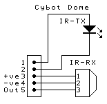
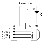
   These
first two circuits are extremely simple, and almost identical - the only
difference being the pin connections to the plug, assuming the colour
codes on the wires are used correctly they are wired the opposite way
around. The circuits both use a single IR diode for a transmitter, there's
no series current limiting resistor on either board, so presumably that
will be mounted on the boards they connect to. The receivers look to be
fairly standard IR receiver I/C's, although they are physically smaller
than the usual type - these usually require a pull-up resistor on the
output pin, and decoupling components on the +ve supply, again presumably
they will be mounted on the boards they connect to. These IR receivers are
very simple to use, you supply them with a decoupled 5V supply, and it
outputs a demodulated signal at the output pin. IR communications modulate
the IR light at around 38-40KHz, these I/C's detect and amplify the IR
light signal, provide automatic gain control (AGC), detect the 38-40KHz
modulation, and pull the output low while it's being received. You
generally have to implement some kind of special coding technique, as RR
state that there will be 16 possible channels (which uses 4 bits), and
presumably they will send an 8 bit data byte, making a 12 bit word - not
counting any possible start or stop bits. Stop bits are not usually used
for IR, but start bits are pretty well essential. As soon as we get
something transmitting I'll analyse the coding system used and post the
details. These
first two circuits are extremely simple, and almost identical - the only
difference being the pin connections to the plug, assuming the colour
codes on the wires are used correctly they are wired the opposite way
around. The circuits both use a single IR diode for a transmitter, there's
no series current limiting resistor on either board, so presumably that
will be mounted on the boards they connect to. The receivers look to be
fairly standard IR receiver I/C's, although they are physically smaller
than the usual type - these usually require a pull-up resistor on the
output pin, and decoupling components on the +ve supply, again presumably
they will be mounted on the boards they connect to. These IR receivers are
very simple to use, you supply them with a decoupled 5V supply, and it
outputs a demodulated signal at the output pin. IR communications modulate
the IR light at around 38-40KHz, these I/C's detect and amplify the IR
light signal, provide automatic gain control (AGC), detect the 38-40KHz
modulation, and pull the output low while it's being received. You
generally have to implement some kind of special coding technique, as RR
state that there will be 16 possible channels (which uses 4 bits), and
presumably they will send an 8 bit data byte, making a 12 bit word - not
counting any possible start or stop bits. Stop bits are not usually used
for IR, but start bits are pretty well essential. As soon as we get
something transmitting I'll analyse the coding system used and post the
details.
 As
usual I'll be adding the extra board details as I receive them, in the
meantime if you want to know more about IR communications I have details
of how to make your own in my
PIC Tutorial Series. As
usual I'll be adding the extra board details as I receive them, in the
meantime if you want to know more about IR communications I have details
of how to make your own in my
PIC Tutorial Series.
|

